1. 📞 Serial Communication Intro
☝︎ home
☞ next chapter: Max to Arduino - A Digital Output controlled from Max
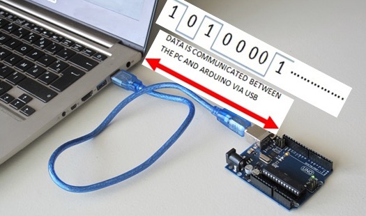
Serial communication is a simple means of sending data quickly and reliably from one device to another. The data is sent, one bit at a time, one right after the other, over a single line. The data packages are electrical pulses, 5 volts represents a bit value of 1, and 0 volts a 0. In Arduino this equals setting a pin HIGH or LOW. It's a little like Morse code, where you can use dits and dahs to send messages by telegram.
A minimum of three lines or wires are used for bidirectional communication: transmit (TX), receive (RX), and ground (GND).
See this tutorial is you want to read more on the basics of Serial Communication.
Serial Communication with Arduino
All Arduino boards have at least one serial port (also known as a UART or USART). It communicates on digital pins 0 (RX) and 1 (TX). The Arduino Uno boards we use have a chip to convert the hardware serial port on the Arduino chip to USB. Not all Arduino boards have this.

We've actually used the Serial communications capability already quite a bit as that is how we send sketches to the Arduino! When you Compile/Verify what you're really doing is turning the sketch into binary data (ones and zeros). When you Upload it to the Arduino, the bits are shoved out one at a time through the USB cable to the Arduino where they are stored in the main chip.
This is a good introductory tutorial on using serial communication (input) with Arduino.
Interfacing Max with Arduino and vice versa
This is accomplished using the serial functionality of the Arduino and the serial object in Max.
In the following pages there is almost no code included. You will always need to open the files in their respective applications: Arduino & Max.
👉🏻 Download the code examples for this tutorial as a zip file. 👈🏻

