☝︎ home
☞ next chapter: Max to Arduino - Analog output(s) controlled from Max
g1. Max to Arduino: Analog output controlled from Max
We reverse the communication again. Max is the sender, Arduino the receiver. There are 2 examples included. In the first we send the data in bytes (values between 0 and 255). In the 2nd we send an ASCII encoded string of values from 0 to 255. Each sequence is concludes with a newline character. Both examples are included in the max patch but there are 2 different Arduino sketches.
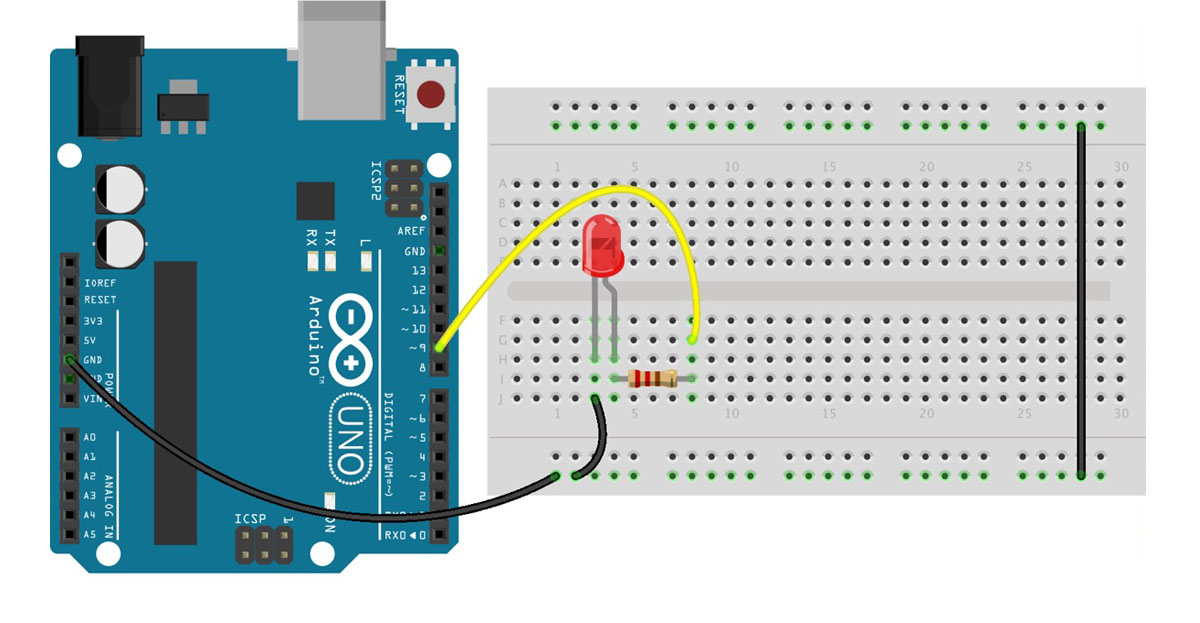
 a basic circuit with an external LED and resistor
In Arduino we the analogWrite() function to generate an analog value to a pin. This is not a true analog output.
You'll find explanation and clarification in the code examples as comments.
The file 'getMaxBufferValue.js' is needed for a calculation in Max.
g2. Max to Arduino: More Analog outputs controlled from Max
This example is similar to the example above where an ASCII encoded string of values is sent from Max. We now send all 3 values concluded with a newline character.
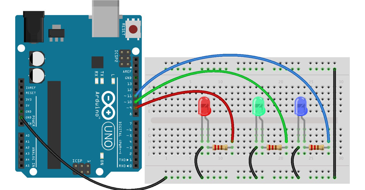
 3 external LEDs are now connected to the Arduino
NOTE:
On using an RGB LED and why sharing one resistor on the common anode or cathode is not a good idea.
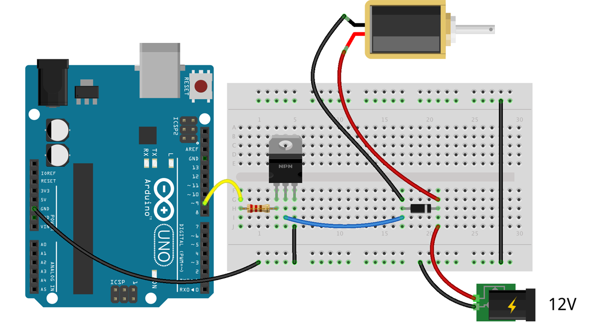
g3. Max to Arduino: solenoid(s)
🚧 🚧 🚧 🚧 🚧 🚧 🚧 🚧

see https://adam-meyer.com/arduino/TIP120
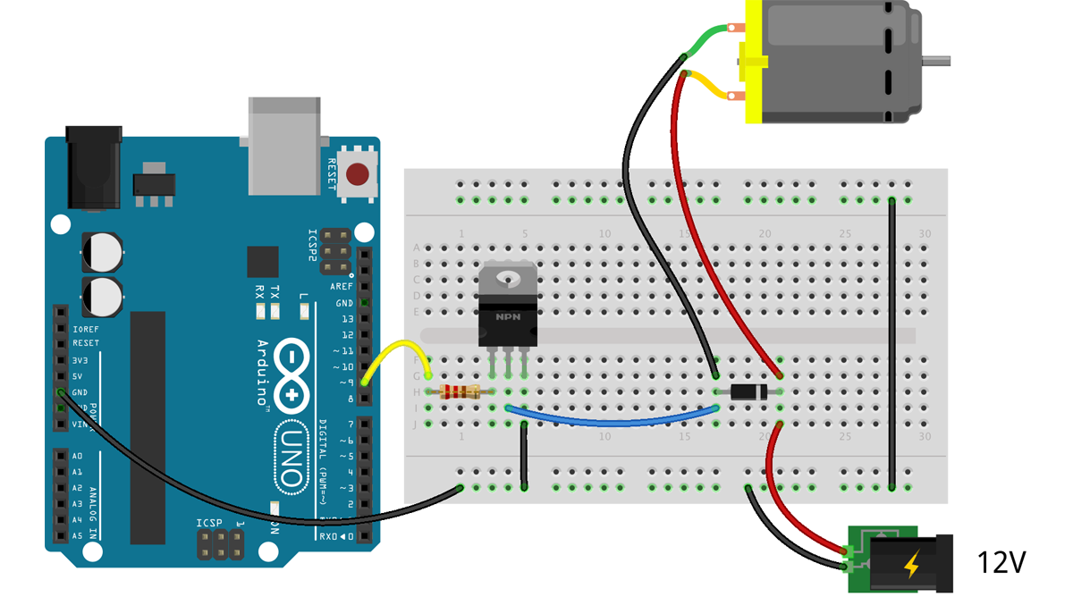
g4. Max to Arduino: dc motor(s)
🚧 🚧 🚧 🚧 🚧 🚧 🚧 🚧

see https://adam-meyer.com/arduino/TIP120

